REPORT SUMMARY
Engineering question and conclusion
Can a computationally practical, verified 2D axisymmetric Navier–Stokes model quantify flow around a generic intravascular device and supply consistent training data for design optimization?
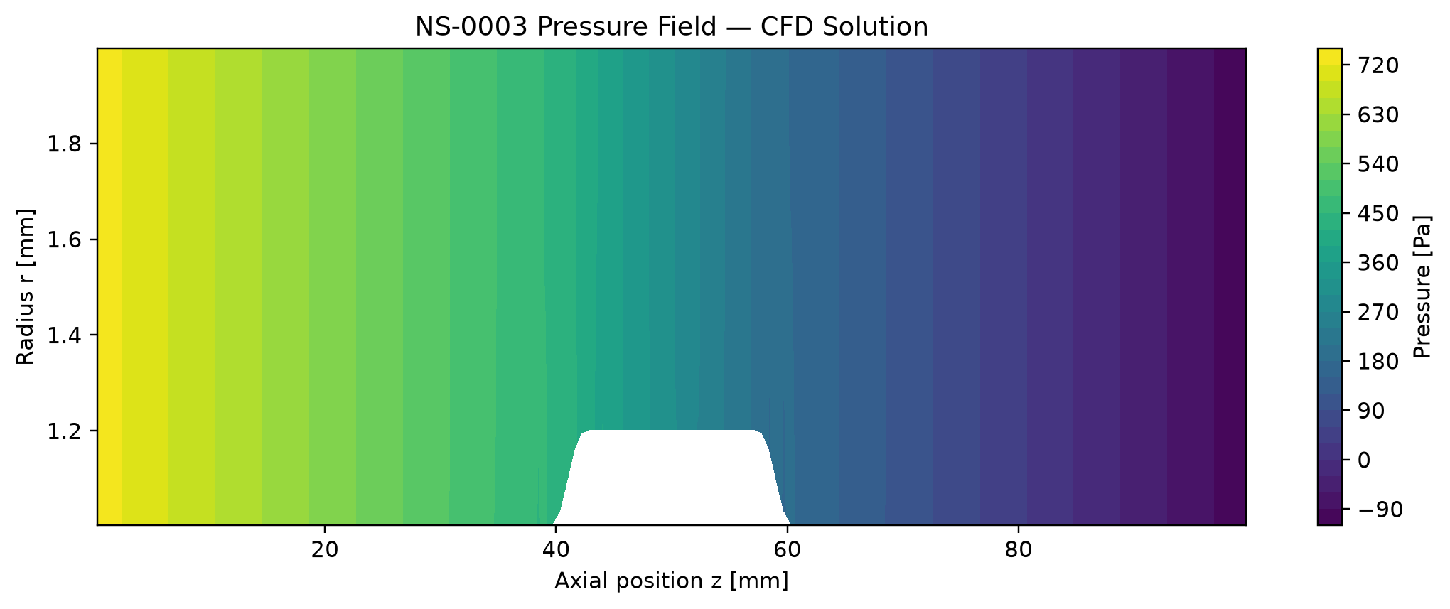
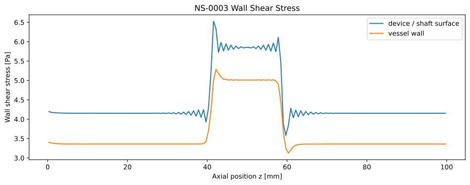
The NS–0003 baseline models a smooth enlarged body on a continuous catheter shaft inside a 4 mm vessel at 100 mL/min. The coupled solver converged on the 161 × 41 production grid. Pressure drop was 846.262 Pa, peak velocity 0.314003 m/s, and device maximum wall shear 6.525 Pa. A three-grid study supports the medium mesh for the declared parametric dataset, while wall shear retains an explicit numerical-quality qualification.
A separately run candidate, OPT1–001, passed its solver gate and reduced the computed pressure drop to 752.932 Pa. These are numerical engineering results for a generic model. They are not experimental, patient-specific, or clinical validation.
01 / PHYSICAL MODEL
Geometry and operating point
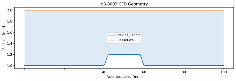
The 100 mm domain is a concentric annulus between a rigid vessel wall and a continuous solid shaft. A local enlarged device body is joined to the shaft by smooth C² transitions. The solver uses a meridional (z, r) domain revolved about the axis; this is axisymmetric cylindrical CFD, not planar Cartesian flow. The model has no free-ended centerline tip.
| Vessel inner diameter | 4.0 mm |
|---|---|
| Continuous shaft OD | 2.0 mm |
| Device body OD / length | 2.4 mm / 15 mm |
| Upstream / downstream transition | 3 mm / 3 mm, C² smooth |
| Minimum radial clearance | 0.8 mm |
| Axial domain / device center | 100 mm / 50 mm |
| Volumetric flow rate | 100 mL/min (1.667 × 10⁻⁶ m³/s) |
|---|---|
| Density ρ | 1060 kg/m³ |
| Dynamic viscosity μ | 0.0035 Pa·s |
| Flow / material model | Steady, incompressible, Newtonian, laminar |
| Walls / symmetry | Rigid, no slip; axisymmetric, no swirl |
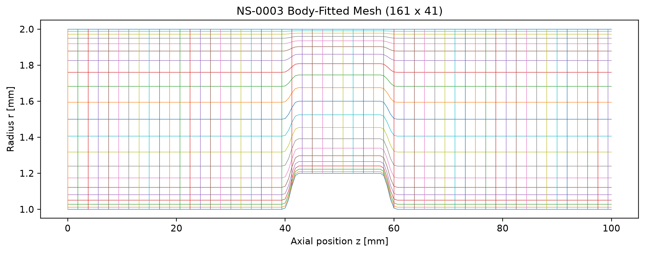
| Production grid | 161 axial × 41 radial nodes; β = 1.8 |
02 / GOVERNING PHYSICS
Equations, boundaries, and method
The solved velocity is u = (uz, ur) with uθ = 0 and no circumferential gradients. The steady incompressible cylindrical equations are:
Volume flow and Newtonian wall shear are extracted as Q = 2π∫ uzr dr over a cross section and |τw| = μ |∂ut/∂n|wall. The radial momentum equation includes the cylindrical vector-Laplacian term −μur/r².
Boundary conditions
- Inlet: prescribed 100 mL/min mass flow through the annulus.
- Outlet: pressure reference and outflow treatment in the coupled solver.
- Device and vessel: stationary no slip and no penetration.
- Azimuth: rotational symmetry; no swirl.
Numerical implementation
- Body-fitted, cell-centered, conservative axisymmetric finite-volume geometry with revolved face areas and cell volumes.
- Implicit axial/radial momentum predictor; first-order upwind convective fluxes and geometry-consistent wall diffusion.
- Pressure correction, conservative face-flux correction, and velocity/pressure under-relaxation (0.7 / 0.2).
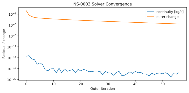
- Iteration stops when continuity ≤ 10⁻⁹ kg/s and outer flux change ≤ 2 × 10⁻⁵; both conditions are required.
The repository's general numerical-method note includes historical NS–0002 development status. The method summary here follows the NS–0003 solver implementation and frozen model record at the evidence commit. Inspect NS–0003 solver ↗
03 / SOLVER OUTPUT
Computed solution fields
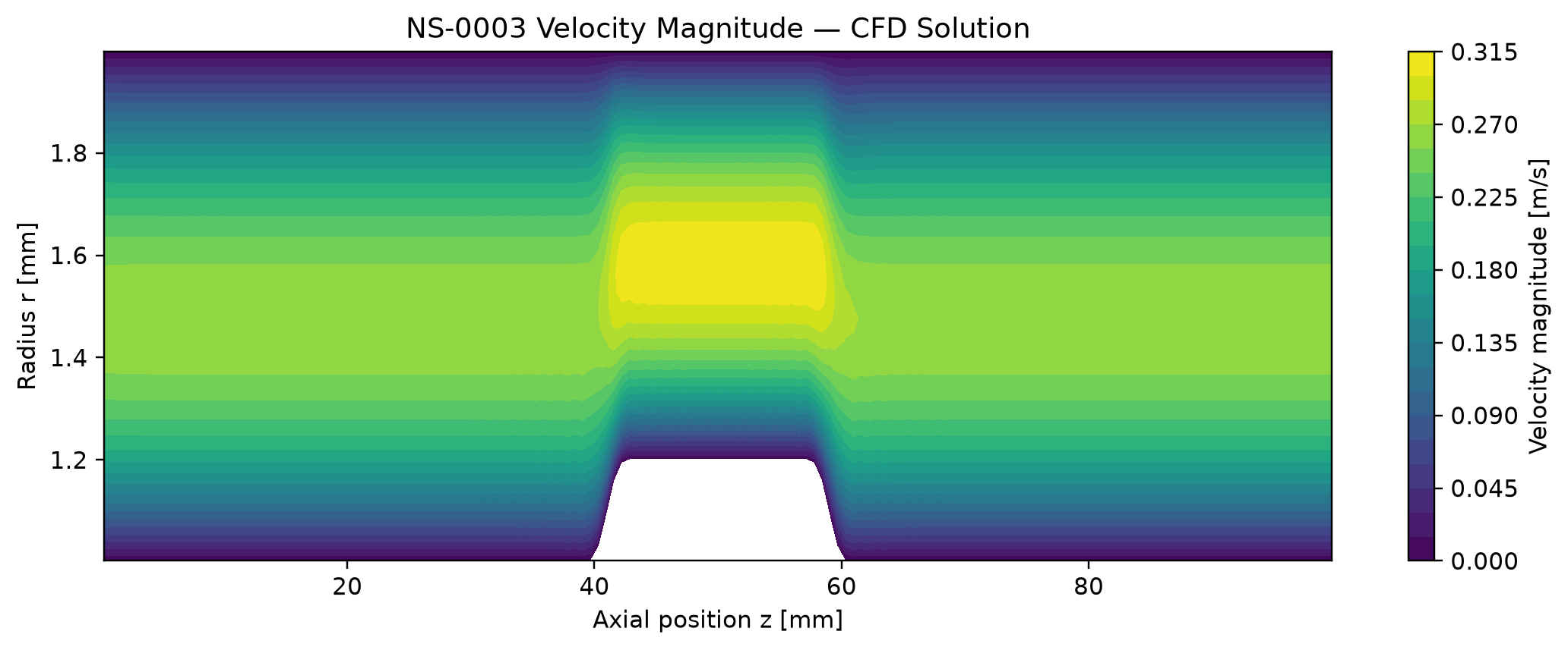
Switch cases to inspect their actual saved figures. Numeric comparison stays visible below. The color range is set separately in each source figure, so compare the reported values rather than color alone.
| Output | Baseline | OPT1–001 | Change vs baseline |
|---|---|---|---|
| Static pressure drop | 846.262 Pa | 752.932 Pa | −11.03% |
| Peak velocity magnitude | 0.314003 m/s | 0.277215 m/s | −11.72% |
| Device max WSS | 6.525 Pa | 4.547 Pa | −30.31% · qualified |
| Device P95 WSS | 5.909 Pa | 4.473 Pa | −24.30% · qualified |
| Vessel max WSS | 5.289 Pa | 3.709 Pa | −29.86% · qualified |
| Solver iterations | 57 | 56 | Both converged |
Percentage change = (OPT1–001 − baseline) / baseline × 100, using the stored solver results. Static pressure is gauge-dependent; pressure drop is the reported comparison quantity.
04 / NUMERICAL CREDIBILITY
Verification and mesh decision
The baseline solve passed both recorded stopping gates. Three systematically refined NS–0003 grids converged and conserved mass. The 161 × 41 mesh was frozen for dataset production because bulk pressure and velocity responses changed little against 201 × 51; wall-shear sensitivity is larger and remains qualified.
| Grid | Nodes | Iterations | Δp (Pa) | Peak |u| (m/s) | Device P95 WSS (Pa) |
|---|---|---|---|---|---|
| Coarse | 121 × 31 | 42 | 841.838 | 0.313769 | 6.006 |
| Production | 161 × 41 | 57 | 846.262 | 0.314003 | 5.909 |
| Fine reference | 201 × 51 | 71 | 851.358 | 0.314234 | 5.716 |
| Gate | Acceptance | Baseline | OPT1–001 |
|---|---|---|---|
| Continuity | ≤ 1 × 10⁻⁹ kg/s | 7.36 × 10⁻¹⁹ kg/s · pass | 9.38 × 10⁻²⁰ kg/s · pass |
| Outer flux change | ≤ 2 × 10⁻⁵ | 1.956 × 10⁻⁵ · pass | 1.908 × 10⁻⁵ · pass |
| Inlet/outlet mass imbalance | Recorded with solver gate | 2.17 × 10⁻¹⁹ kg/s | 2.17 × 10⁻¹⁹ kg/s |
The three-grid study is for the frozen baseline engine. OPT1–001 passed its own solver gate on the production grid, but a separate fine-grid study for that candidate is not recorded here. Three-grid data ↗ · Decision D-013 ↗
05 / ENGINEERING MEANING
Interpretation, scope, and limitations
The enlarged baseline body reduces the open annular area locally and accelerates flow around the device. The recorded OPT1–001 geometry has a smaller body OD and produces lower computed pressure drop, peak velocity, and wall-shear maxima at the same flow rate. This is a within-model design comparison, independently rerun with the frozen CFD solver after candidate selection.
Device P95 WSS changes 3.374% from medium to fine; wall-gradient outputs should carry that uncertainty flag. The OPT1–001 candidate has no independent three-grid study in this package.
Steady, rigid-wall, incompressible Newtonian, laminar, concentric, 2D axisymmetric geometry. No pulsatility, eccentricity, 3D flow, FSI, or patient-specific anatomy is modeled.
The solid is a continuous shaft with a local enlarged body. It is not a free-ended catheter tip. Separate free-ended-tip experiments remain unconverged in the latest development log.
No experimental or clinical validation is reported. CFD verification establishes numerical behavior for the declared model, not medical safety, efficacy, or general-device performance.
SOURCE & REPRODUCTION
Traceable result package
Evidence was read from private repository commit 695403bf71dcac1f884dcb1fd3ba786836fbecc7 ↗ on 23 September 2026. The figures and values on this page are a static snapshot, not live results. GitHub evidence links require collaborator access.
NS–0003 / CFD Physics Engine v1 · Engineering report · Snapshot 23 Sep 2026